Chapter 3 - Digital System and Logic Design
Comprehensive Questions & Answers for Class 9 Computer Science (Punjab Board)
Boolean Function
Boolean function:
A Boolean function is a function which has one or more binary inputs and produces a single binary output.
The input and output can only have two values:
- False: represented by 0
- True: represented by 1
Example:
Consider a Boolean function with two inputs, A and B. We can construct function F that represents the AND Operation.
Y = F(A, B) = A · B
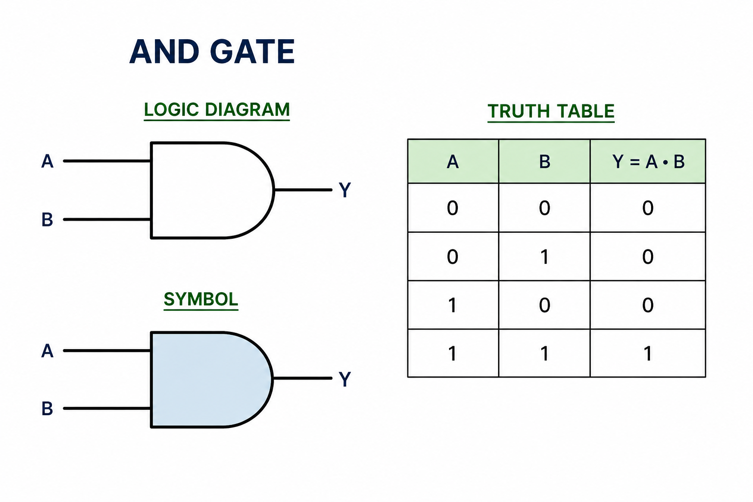
The diagram shown above demonstrates a basic digital Circuit, which is an AND gate.
- The box symbolizes the AND function Y = F(A, B) = A · B.
- The box has two inputs A and B.
- Rule: If both A and B are 1, the output will be 1. If any other case, the output will be Zero.
- The inputs are shown at the entrance of box, while Output is depicted at the exit of the block.
Significance of Truth Table
Digital logic:
Digital logic is the basis of digital Systems. It involves the use of binary numbers that is 0 and 1, to represent and manipulate Information. Digital logic circuits use these binary values to perform various operations, and they are essential to the functioning in operation of Computers.
Significance of Truth Table:
In digital Circuits, the two States 0 and 1 are represented by different Voltage levels.
Logic Levels:
- Binary "1" = Higher voltage, Such as 5 volts
- Binary "0" = Low voltage, for instance 0 volts
These Voltage levels are termed as logic levels.
Analog Signals vs Digital Signals
| Analog Signals | Digital Signals |
| Definition: Analog Signals are Signals that change with time Smoothly and Continuously over time. | Definition: Digital Signals has discrete time. |
| Range: They Can have any value within given range. "Infinite possible values". | Range: They have only two values "0" and "1". |
| Example: They are used in Sound waves, BP. | Example: They are used in Computer, as binary data. |
Not Gate
Logic Gates:
Logic gates are physical devices in electronic Circuits that perform Boolean Operations.
Not Gate:
Definition: It Implements the NOT function.
Function of Not Gate:
It gives outputs the opposite of the input.
Rule: If input is 1 then output will be 0, and if input is 0 then output will be 1.
Truth Table Of Not Gate:
| P | P(NOT) |
| T | F |
| F | T |
Purpose of a Karnaugh Map
Karnaugh Map:
A Karnaugh Map is a graphical representation which can be used to solve boolean algebra expressions and minimize a logic function where algebraic computations are not employed.
Purpose Of K-Map:
It is a technique in which truth values of Boolean function is plotted to enable the identification of patterns and to perform term combining for simplification.
Usage of Boolean function
Boolean function:
A Boolean function is a function which has one or more binary input and produces a Single binary output. It contain only two values:
- True (1)
- False (0)
Usage in Computer:
There are many Uses of Boolean functions in the Computer for various Operations.
1. Arithmetic Operations:
Boolean functions are used in Arithmetic logic units (ALUs) of CPUs to perform operation like addition, Substraction, multiplication and even division.
2. Data Processing:
Boolean functions are used to process binary data in memory and Storage devices, ensuring efficient data manipulation and retrieval.
3. Control Logic:
Boolean functions are applied in computers to control various parts of the system's Operation to function in co-ordinated manner.
Construction of Truth Table for Boolean Expression
Construction of Truth Table:
The Construction of Boolean expression is done by employing the basic logical operations Such as AND, OR, NOT, which connect the input to generate the Correct output.
Example:
Consider a Boolean function with two inputs A and B. We can construct function F that represents the AND operation:
Function: Y = F(A, B) = A · B
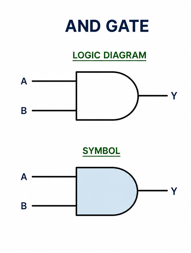
The diagram shown above demonstrates a basic digital Circuit, which is an AND gate.
- The box symbolizes the AND function Y = F(A,B) = A·B.
- This box has two Inputs: A and B.
- Rule: If both A and B are 1, the output will be 1. In any other case, the Output will be 0.
- The Inputs are shown at the entrance of the box, while the output is displayed at the exit of the block.
Truth Table for AND Gate:
| A | B | Y = F(A, B) = A · B |
| 0 | 0 | 0 |
| 0 | 1 | 0 |
| 1 | 0 | 0 |
| 1 | 1 | 1 |
Concept of Duality in Boolean Algebra
Boolean Algebra:
Boolean algebra is the branch of mathematics related to logic and symbolic computation, using two values namely True and False.
Binary variables and Logic operations:
- Binary variables that can have only two values: 0 and 1.
- Logic operations are basic operations implemented in Boolean algebra for processing of these binary Variables.
- The primary logic operations are AND, OR and NOT.
AND Operation:
- AND is the basic logic operator which is used in Boolean algebra.
- It requires two binary inputs which will give a Single binary output.
- The Symbol · is used for an AND operation.
- The output of AND operation is 1 only when both Inputs are 1. Otherwise the result is 0.
Example:
Consider two binary variables:
- A = 1 (True)
- B = 0 (False)
The AND operation can be written as:
P = A · B
In this example: A = 1 , B = 0. Then, the result P of the AND Operation is 0 (False)
Truth Table for AND Gate:
| A | B | A AND B (P) |
| 0 | 0 | 0 |
| 0 | 1 | 0 |
| 1 | 0 | 0 |
| 1 | 1 | 1 |
Half-Adder vs Full-Adder
| Half-Adder | Full-Adder |
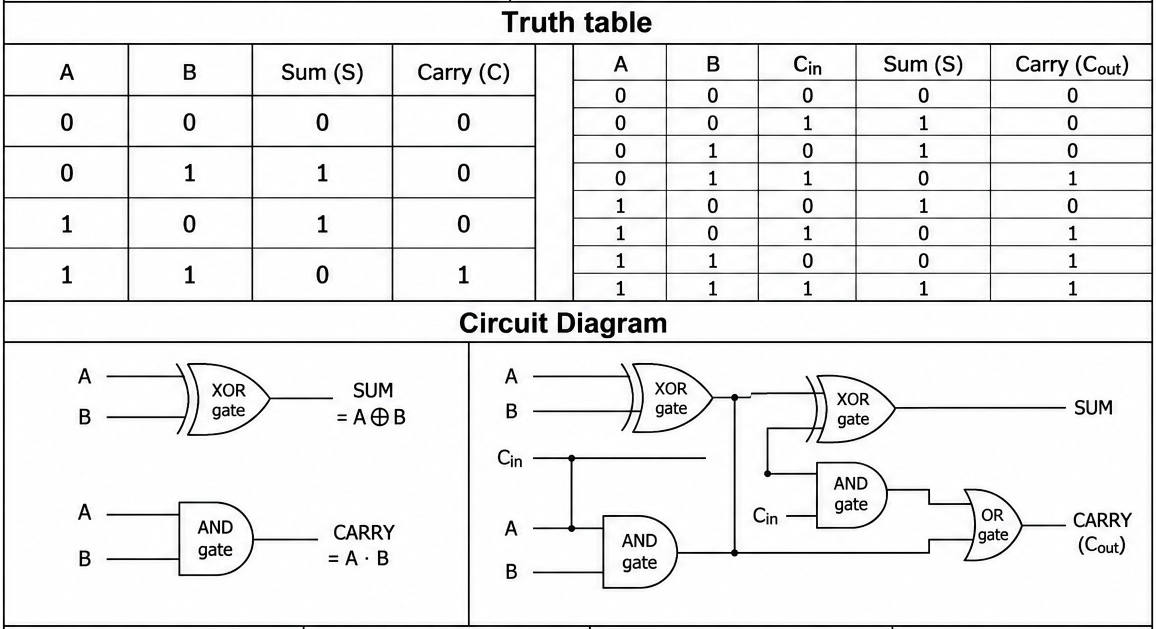
| A half-adder is a basic Circuitry Unit that performs addition of two Single-bit binary digits. | A full-adder is a more Complex Circuit that adds three Single-bit binary digits. |
| Input and Output | |
| It has two Inputs: A and B and two outputs: Sum(S) and the carry(C). | It has three Inputs A, B and Cin and two outputs: Sum(S) and Carry(Cout). |
| Boolean Expression | |
| S = A ⊕ B | S = A ⊕ B ⊕ Cin |
| C = A · B | C = (A·B) + (Cin·(A⊕B)) |
Karnaugh maps simplify Boolean Expressions
To simplify the Boolean expression $$A.\bar{B}+\bar{A}.B+A.B$$ using a Karnaugh map:
1. Expression: $$A.\bar{B}+\bar{A}.B+A.B$$
Step 1: Draw K-map for two variables A and B
| $$\bar{B}=0$$ | $$B=1$$ | |
| $$\bar{A}=0$$ | $$0$$ | $$1$$ |
| $$A=1$$ | $$1$$ | $$1$$ |
Step 2: Fill the K-map
Determine the output for each combination of A and B based on the expression:
For A=0 and B=0:
$$F=A.\bar{B}+\bar{A}.B+A.B$$
$$=0\cdot1+1\cdot0+0\cdot0=0$$
For A=0 and B=1:
$$F=A.\bar{B}+\bar{A}.B+A.B$$
$$=0\cdot0+1\cdot1+0\cdot1=1$$
For A=1 and B=0:
$$F=A.\bar{B}+\bar{A}.B+A.B$$
$$=1\cdot1+0\cdot0+1\cdot0=1$$
For A=1 and B=1:
$$F=A.\bar{B}+\bar{A}.B+A.B$$
$$=1\cdot0+0\cdot1+1\cdot1=1$$
Step 3: Group the 1s in the K-map
Group adjacent 1s to simplify the expression.
| $$\bar{B}=0$$ | $$B=1$$ | |
| $$\bar{A}=0$$ | $$0$$ | $$1$$ |
| $$A=1$$ | $$1$$ | $$1$$ |
From K-map, we can form groups:
1. Group of two 1s in the second column:
$$\bar{A}.B+A.B$$
$$=(\bar{A}+A)\cdot B$$
$$=1\cdot B$$
$$=B$$
2. Group of two 1s in the second row:
$$A.\bar{B}+A.B$$
$$=(\bar{B}+B)\cdot A$$
$$=1\cdot A$$
$$=A$$
Final Simplified Expression:
$$F(A,B)=B+A$$
4-bit Binary Adder Design
Designing a 4-Bit Binary Adder:
A 4-bit binary adder adds two 4-bit binary numbers, A(A3, A2, A1, A0) and B(B3, B2, B1, B0), producing a 4-bit Sum (S3, S2, S1, S0) and a Carry-out (Cout). It combines half-adders (HA) and full adders (FA) for efficient Computation.
Steps in design:
Step 1: Understanding Half-Adders and Full Adders
1. Half-Adder (HA):
- Input: Two bits (A and B)
- Output: Sum(S) and Carry (C)
- Boolean Expression: Sum = A ⊕ B , Carry = A . B
Truth Table:
| A | B | S (A⊕B) | C (A.B) |
| 0 | 0 | 0 | 0 |
| 0 | 1 | 1 | 0 |
| 1 | 0 | 1 | 0 |
| 1 | 1 | 0 | 1 |
2. Full Adder (FA):
- Inputs: Two bits (A and B) plus a carry-in (Cin)
- Outputs: Sum (S) and Carry-out (Cout)
- Boolean Expressions: S = A ⊕ B ⊕ Cin , Cout = (A . B) + (Cin . (A ⊕ B))
Truth Table:
| A | B | Cin | S (A⊕B⊕Cin) | Cout |
| 0 | 0 | 0 | 0 | 0 |
| 0 | 0 | 1 | 1 | 0 |
| 0 | 1 | 0 | 1 | 0 |
| 0 | 1 | 1 | 0 | 1 |
| 1 | 0 | 0 | 1 | 0 |
| 1 | 0 | 1 | 0 | 1 |
| 1 | 1 | 0 | 0 | 1 |
| 1 | 1 | 1 | 1 | 1 |
Step 2: 4-Bit Adder Construction
1. First Stage (Least Significant Bit):
Use a half-adder (HA) to add the first bits of A and B (A0 and B0)
- Sum S0 = A0 ⊕ B0
- Carry C0 = A0 . B0
2. Remaining Stages (A1, A2, A3):
Use full-adders (FA) to add Subsequent bits along with the Carry-in from the previous stage.
- Sn = An ⊕ Bn ⊕ Cin
- Cout = (An . Bn) + (Cin . (An ⊕ Bn))
Step 3: Final Carry-out:
The Carry-out C3 from the final full-adder is the overall Carry of operation.
Truth Table:
| A1 | A0 | B1 | B0 | Cin | S1 | S0 | Cout |
| 0 | 0 | 0 | 0 | 0 | 0 | 0 | 0 |
| 0 | 0 | 0 | 1 | 0 | 0 | 1 | 0 |
| 0 | 0 | 1 | 1 | 0 | 1 | 0 | 0 |
| 1 | 1 | 1 | 1 | 0 | 1 | 1 | 1 |
Step 4: Logic Diagram
Stage 1: Connect a half-adder for A0 and B0.
Stage 2: Use full-adder for A1, B1 and Carry from S1
Stages 3 & 4: Repeat for A2, B2 and A3, B3.
By Combining the outputs of each Stage, the 4-bit adder produces a Sum S3, S2, S1 and the final Carry-out.
Simplification of Given Boolean function Using Boolean Algebra Rules
F(A,B) = A.B + A. B̄
F(A,B) = A . (B + B̄) (Distributive Law)
F(A,B) = A . 1 (Complement Law)
F(A,B) = A (Identity Law)
So, F(A,B) = A
De Morgan's Law
Use De Morgan's Law to Simplify:
$$F(A,B,C) = \overline{A+B} + \overline{A.C}$$
= Ā. B̄ + Ā + C̄ (by De Morgan's Law)
= (Ā. B̄) + Ā + C̄
= Ā + C̄ (by using absorption law)
Simplification of Given Expressions
- $$\overline{A+B}$$ • (A+B)
= A̅ • B̅ • (A+B) (by using De Morgan's law)
= A̅ • B̅ • A + A̅ • B̅ • B (by using distributive law)
= A̅ • A • B̅ + A̅ • B̅ • B (by using commutative law)
= 0 • B̅ + A̅ • 0 (by using complement law)
= 0 + 0 (by using null law)
= 0 -
(A + B̅) • (A̅ + B)
let. A + B̅ = C
= C • (A̅ + B)= C • A̅ + C • B (by using Distributive Law)
= (A + B̅) • A̅ + (A + B̅) • B (putting value of C)= (A • A̅) + B̅ • A̅ + A • B + B̅ • B (by using Distributive Law)
= 0 + B̅ • A̅ + A • B + 0 (by using Complement Law: A.A̅ = 0)
= B̅ • A̅ + A • B (by using Identity Law: 0 + X = X)
= A̅ • B̅ + A • B (by using Commutative Law: B̅.A̅ = A̅.B̅) -
A + A̅ • (B̅ + C)
= A + A̅ • B̅ + A̅ • C (by using Distributive Law)
= A + A̅ • (B̅ + C) (by using Distributive Law)
= A + B̅ + C (by using Redundancy Law: A + A̅.X = A + X) - $$\overline{A.B}$$ + A.B
= $$\overline{A.B}$$ + A·B
= 1 (by Complement Law: X + X̅ = 1)
e. (A·B) + (A̅·B̅)
= (A·B + A̅)·(A·B + B̅) (by Distributive Law)
= (A + A̅)·(B + A̅)·(A + B̅)·(B + B̅) (by Distributive Law)
= (1)·(B + A̅)·(A + B̅)·(1) (by Complement: X+X̅=1)
= (A̅ + B)·(A + B̅) (Final simplified form)